When a facility experiences a catastrophic electrical failure event, the impact of such events can be devastating to operations — and, more importantly, personnel. Just such an event occurred at a gas plant in Alberta, Canada.
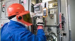
Field service personnel were dispatched to the gas processing plant in northern Alberta to repair a failed 600V motor control center (MCC) bus. Before the technicians arrived, the 600V bus components had been disassembled by facility personnel to prepare for the installation of a new MCC section. Getting the facility back up and operational for the client was more critical than performing an in-depth investigation of the failure.
However, using the information and photographs available, the technicians explored potential root causes for the failure. Moisture, humidity, and condensation were discussed but quickly ruled out due to ambient conditions within a functional climate-control unit in the building, which also provided inherently low relative humidity in this area.

Photo 1 shows that the A-phase bus experienced a high degree of heating between the vertical bus connection and the adjacent horizontal bus connection where the eventual failure occurred. This was apparently due to the high oxidation level on the bus bar exacerbated by the lack of tin plating.
If there were a loose vertical bus connection, it likely would have dissipated heat into the nearby horizontal connection that was thermally and electrically insulated with vinyl tape. This allowed heat to accumulate within this portion of the bus.
At this point, the A-phase bus bar got hot enough to allow the tin plating to melt, and molten tin dripped down on top of the adjacent B-phase bus. This would have effectively created a conductive path between phases, allowing an inadvertent electrical connection, subsequent ionization of surrounding air, and an arc flash event (Photo 2).

The likely root cause of this failure was determined to be loose vertical bus connections that were not recognized during the initial commissioning of the MCC three years prior. As part of the investigation, previous maintenance records on the failed equipment were requested. The client stated that no previous maintenance had been performed, and no maintenance records existed. This was a key contributor to the failure. The deficiency may have been recognized before the eventual catastrophic failure if contact resistance testing had been performed during maintenance.
Lessons learned
The catastrophic failure of this 600V MCC could have been mitigated and potentially avoided during commissioning or maintenance activities by employing several procedures and tools that are available to experienced test technicians, such as:
- Check the torque on all accessible bolted connections.
- Use a higher DC current contact resistance test equipment, if possible, within rated equipment capacity (i.e., a 400A primary-injection test system versus a 10A hand-held contact resistance test set).
- Ensure all vertical bus connections were tested by removing key MCC cells that would allow for maximum bus run lengths for the 400A DC current test.
- Visually inspect the bus where accessible to identify anomalies such as insulating tape or clear plastic wrap trapped under the connection or a layer of corrosion/dirt/oxidation inside the connection.
Recommended tests
When testing bolted electrical connections, several additional test procedures are recommended, including:
- All bolted electrical connections should be tested with a low-resistance ohmmeter. The NETA standard does not specify a DC current value; however, if a higher available test current falls under the confines of the equipment’s rated capacity it should be used, as some high-resistance connections don’t manifest until higher current levels.
- If inspecting a 4,000A bus, consider using a higher-output test set and carefully check the torque on all bolted connections.
- Conversely, if the equipment is only rated for 20A, for example, a 10A DC low-resistance ohmmeter test can be used if torque cannot be confirmed.
- Torque checks should always supplement electrical contact resistance testing if the connections are accessible. Specific items to be considered for testing include:
- Vertical bus connections accessed by temporarily removing MCC buckets.
- Grounding provisions such as safety grounding balls.
- Higher current disconnect switches and breakers (refer to ANSI/NETA ATS and ANSI/NETA MTS for more information).
- Fuse connections (connection only), but be cautious when performing contact resistance around a fuse. A low-current test unit or multimeter can be used if fuse integrity needs to be confirmed.
Theory
Simply put, a high-resistance connection can generally result in two undesirable outcomes:
- Overheating, which leads to melted components and a potentially catastrophic failure.
- Excessive voltage drop, leading to downstream equipment damage.
With loose bolted electrical connections, a hazardous scenario can exist when equipment connections will not sufficiently pass the rated current without overheating. This high-resistance connection can create heating modeled by the P = I2 × R formula, where P is equal to power. This could simply be understood as directly proportional to the heating effect at this poor connection. I and R are equal to current and resistance, respectively.
The heating effect can also be accelerated by items such as well-insulated connections (thermally and electrically), tight enclosed spaces without airflow, and the positive feedback loop of connection having higher resistance as heat increases. A hot general environment (such as an MCC located in a small building with no A/C in the summer) will also accelerate the effects of heating.
Downstream equipment can also experience a voltage drop from heating. The magnitude of this drop can be modeled by V = I × R, where I is nominal bus current, and R is the resistance of the connection. The following quote from Fluke Corp.’s website discusses the effect voltage drop can have on current unbalance on electric motors:
“Voltage unbalance at the motor terminals causes high current unbalance, which can be six to 10 times as large as the voltage unbalance. Unbalanced currents lead to torque pulsation, increased vibration and mechanical stress, increased losses, and motor overheating.
“ANSI/NEMA standard MG 1 prescribes a 1% limit for voltage unbalance, noting that current unbalance can be expected to be six to 10 times the voltage unbalance on a percent basis. If the current unbalance exceeds 10%, the supply voltages should be corrected to less than 1% unbalance, or the motor must be de-rated.”
Conclusion
The effects of high-resistance connections can ultimately lead to issues with electrical equipment and systems. These effects are exponentially proportional and can cause major issues for plant equipment.
Electrical Testing Education articles are provided by the InterNational Electrical Testing Association (NETA), www.NETAworld.org. NETA was formed in 1972 to establish uniform testing procedures for electrical equipment and systems. Today the association accredits electrical testing companies; certifies electrical testing technicians; publishes the ANSI/NETA Standards for Acceptance Testing, Maintenance Testing, Commissioning, and the Certification of Electrical Test Technicians; and provides training through its annual PowerTest Conference and library of educational resources.